How to Choose an Energy Discharge Capacitor?
Choosing an Energy Discharge Capacitor means matching the component to the pulse, not simply choosing the largest capacitance. The right design depends on stored energy, peak voltage, discharge current, repetition rate, and acceptable temperature rise. A capacitor that handles one sharp pulse may overheat during repeated cycles. Small details matter: lead length, busbar layout, and enclosure ventilation can affect performance.
The International Energy Agency’s Batteries and Secure Energy Transitions (2024) describes the expanding role of energy storage, while the U.S. Department of Energy’s Energy Storage Grand Challenge Market Report (2020) surveys storage technologies and markets. These reports offer useful context, but they do not replace application-specific capacitor testing. For power-electronics design, IEC 61071 provides relevant guidance on power capacitors. Check the manufacturer’s pulse-current, voltage, and lifetime data against the actual operating waveform.
A useful starting point comes from power-electronics experts Robert W. Erickson and Dragan Maksimović. Their textbook, Fundamentals of Power Electronics, gives the governing energy relation: “E = ½CV².” In practice, that equation is only the beginning. ESR, ESL, dielectric behavior, safety margins, and discharge conditions also shape a reliable choice. That is easy to overlook. Measure the real pulse profile, verify thermal limits, and reassess assumptions before finalizing a design. A theoretical calculation can look neat; a warm capacitor after repeated testing is less reassuring.
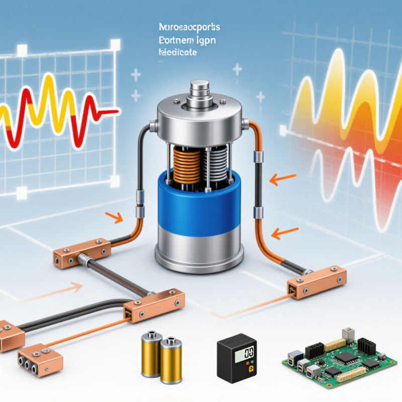
Identify the Application and Required Discharge Energy
Start with the job the capacitor must perform. Is it supplying one short pulse to an actuator, or repeated bursts in a test circuit? Note the load, pulse duration, repetition rate, and acceptable voltage range. A camera-like flash and a motor-start pulse may need similar energy, yet demand very different peak currents.
Estimate the energy required by the load, then allow for losses in wiring, switching components, and the load itself. A capacitor’s stored energy is E = ½CV². If it discharges from Vstart to Vend, the ideal available energy is ½C(Vstart² − Vend²). This helps you estimate capacitance, but it does not predict every real-world result. Check the required voltage, peak current, equivalent series resistance, and temperature rise. Repeated pulses can create heat that a single-pulse calculation misses.
Real circuits are messier. Treat your calculation as a starting estimate, then verify it under the actual load.
Tips: Write down the load’s energy per pulse and pulse rate before comparing capacitors. Leave margin for losses, but avoid choosing a much larger part without checking inrush current and recharge time. Measure the discharge waveform; assumptions can be wrong.
Calculate Capacitance, Voltage, and Pulse Requirements
For an energy-discharge capacitor, begin with the energy your load needs and the voltage available. Use C = 2E/V², where E is joules, V is volts, and C is farads. For a 1,000-joule pulse at 800 volts, the ideal capacitance is about 3.1 millifarads. That is only a starting point.
If the capacitor’s voltage falls during discharge, calculate using the permitted starting and ending voltages: C = 2E/(V₁² − V₂²). IEC 61071:2017 addresses power-electronic capacitors under application-specific electrical stresses; it does not supply one universal pulse-current rating. Check the exact datasheet limits.
Next, estimate pulse current from the waveform, not just stored energy. A rough average is I = CΔV/Δt. Discharging 3.1 millifarads through an 800-volt change in one millisecond implies about 2,500 amperes. That estimate is blunt.
Peak current may be higher, depending on circuit resistance, inductance, and switching behavior. Check peak and RMS current, pulse duration, repetition rate, temperature rise, and equivalent series resistance. A capacitor rated for the voltage may still overheat under repeated pulses.
Include voltage margin for supply variation and switching overshoot, then verify the design with the actual load waveform. I would not trust a single calculation alone. Use IEC 61071 guidance and manufacturer-rated pulse and thermal data to confirm the selection.
Compare Dielectric Types and Discharge Performance
Choosing an energy-discharge capacitor means comparing how its dielectric handles voltage, heat, and repeated pulses. Polypropylene film is often selected for high pulse currents and low dielectric loss. Ceramic parts can be compact, but some high-capacitance types lose capacitance as applied voltage rises. Aluminum electrolytics store substantial energy in a small volume, yet their equivalent series resistance and polarity require careful attention. The details matter.
For discharge speed, compare equivalent series resistance, allowable peak current, and thermal limits—not capacitance alone. A lower resistance can reduce heating during a short, heavy pulse. The stored energy is approximately one-half capacitance multiplied by voltage squared, so a modest voltage increase can sharply raise the energy and stress. Check the actual voltage waveform, pulse duration, and repetition rate.
For context, the 2013 Electricity Storage Handbook, prepared by Sandia National Laboratories with EPRI and NRECA, reports approximately 5–10 Wh/kg and 1–10 kW/kg for electric double-layer capacitors. These figures describe a technology category, not a guaranteed rating for a specific part or a direct film-versus-ceramic comparison. That distinction matters. Bench-test the chosen capacitor under realistic conditions; calculations can miss wiring inductance, temperature rise, and aging. I would not treat one clean pulse as proof of long-term performance.
Check Circuit Compatibility and Safety Requirements
Choose a capacitor by matching capacitance, voltage, pulse current, and waveform to the actual circuit. Measure the highest transient voltage, not just the supply reading. A 470 µF capacitor charged to 400 V stores about 37.6 joules, using the standard energy equation, E = ½CV². That energy can remain hazardous after power is removed. IEEE 519-2022 sets an 8% total voltage-distortion limit at the point of common coupling for systems rated 1 kV or below. That is a system limit, not a capacitor ripple-current rating. Check the harmonic spectrum and temperature rise under real operating conditions. A quiet bench test can miss both.
IEC 61071:2017 covers requirements and tests for power-electronic capacitors; use it to check electrical and thermal suitability. Confirm polarity, peak voltage, ripple current, pulse duration, and permitted dV/dt against the circuit’s worst case. Then size the discharge resistor for the required voltage-decay time and its pulse-energy rating. With a simple RC discharge, five time constants reduce the initial voltage to about 0.7%. Still, verify the voltage with a rated meter before touching terminals. Measure twice. Enclosures, resistor tolerances, and failed components can change the real discharge time. I would not treat a calculated decay as proof of safe isolation.
How to Choose an Energy Discharge Capacitor
Stored energy at 400 V DC rises with capacitance, calculated using E = ½CV². Choose a capacitor whose voltage rating exceeds the circuit’s maximum voltage, including foreseeable transients, and whose capacitance and pulse-current ratings suit the application. Verify discharge-resistor sizing, component power ratings, and safe discharge time; stored energy can remain hazardous after power is removed.
Verify Service Life and Performance Under Operating Conditions
An energy-discharge capacitor can look suitable on a datasheet and still age quickly in service. Verify it at the actual pulse voltage, energy, repetition rate, and ambient temperature—not only at room temperature. Heat changes the picture. Measure case temperature and, where practical, estimate internal heating from ESR and pulse current. Record capacitance, leakage current, and ESR before testing, then repeat measurements after a defined number of cycles. Even a modest capacitance shift can matter when timing or delivered energy is tightly controlled.
Ask for endurance data that resembles your application, including discharge duration, recovery interval, mounting, and cooling conditions. Stay within the specified voltage and temperature limits, and check whether repeated pulses cause performance to drift. Look for stable output, not just survival. A capacitor that remains intact may still have excessive ESR or reduced capacitance. Test setups are never perfect; probe placement and temperature readings can introduce uncertainty. Note those limits, and repeat borderline measurements before making a selection. Recheck the assumptions when the operating pattern changes.



 Customer Support
 Request Sample
 Contact