contact-button

What Is an Industrial Laser Cutter and How Does It Work?

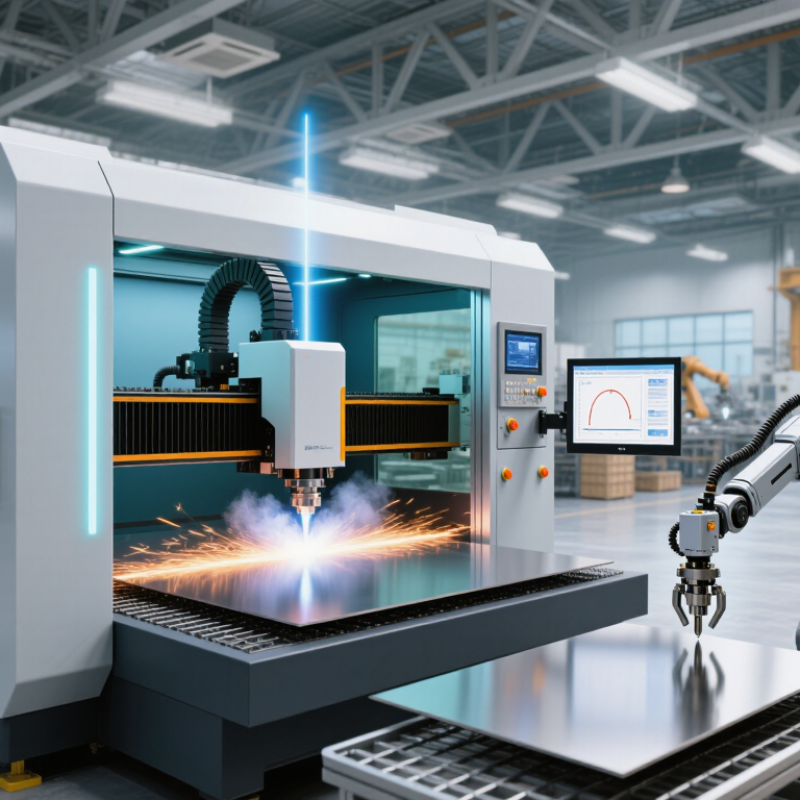
An Industrial Laser Cutter is a computer-controlled machine that uses concentrated light to cut metal, plastics, wood, and other engineered materials. Its beam travels through optics and focuses into a tiny, intense spot. The material melts, burns, or vaporizes. Assist gas then clears the cut zone. Small detail. The result can be a sharp edge measured in fractions of a millimeter.

This technology now sits inside a wider automation movement. The International Federation of Robotics reported 541,302 industrial robots installed worldwide in 2023, showing how manufacturers increasingly connect machines, software, and production data. Industry reports from Grand View Research and MarketsandMarkets also identify fiber lasers, automated handling, and smart manufacturing as important growth drivers. Their market estimates differ because research firms define “industrial laser” differently. That difference deserves attention.

In a modern factory, a fiber laser may cut a stainless-steel sheet while sensors monitor power, speed, focus, and heat. Operators select a programmed path, but the machine still depends on accurate material settings and regular maintenance. A dirty lens can widen the kerf. Poor gas pressure can leave rough edges. The process is powerful, not effortless.

This guide explains the core components, cutting sequence, material behavior, and practical advantages of an Industrial Laser Cutter. It also considers limitations, operating costs, and safety expectations. Guidance from the Laser Institute of America and applicable ANSI laser-safety standards remains essential. Performance claims should be tested on real parts, not accepted from brochures alone. That is where professional judgment begins.

What Is an Industrial Laser Cutter and How Does It Work?

Definition and Core Purpose of an Industrial Laser Cutter

An industrial laser cutter is a computer-controlled machine that uses a concentrated light beam to cut, pierce, or engrave materials. Its core purpose is controlled material separation. The beam melts, burns, or vaporizes a narrow path, while assist gas removes debris from the cut zone. A motion system guides the cutting head across sheet metal, tube, plastic, wood, or composite panels.

Unlike a handheld tool, an industrial system combines a laser source, focusing optics, motion controls, software, and extraction equipment. Operators load a digital drawing, select material settings, and monitor heat, speed, and gas pressure. On a steel sheet, the result may be a clean edge with a thin heat-affected zone. Small errors still matter. A dirty lens can widen the cut and spoil several parts. According to Grand View Research’s 2024 laser cutting machine report, the global market is projected to grow at about 7.5% annually through 2030. This growth reflects demand for repeatable production and reduced setup time, not just higher cutting speed. The International Energy Agency reported that industry used about 37% of global final energy in 2022, so efficient processing deserves attention. Yet laser cutting is not automatically efficient. Power settings, scrap rates, maintenance, and operator training can change the real result.

Key Components and Their Functions

What Is an Industrial Laser Cutter and How Does It Work?

An industrial laser cutter uses a concentrated light beam to cut, mark, or shape materials. The laser source creates intense energy inside a controlled chamber. Mirrors or fiber optics guide this energy toward the cutting head. A focusing lens reduces the beam to a tiny, powerful point. Heat then melts, burns, or vaporizes the material along a programmed path. The CNC controller coordinates speed, movement, and power with precise timing. Small changes matter.

Key Components and Their Functions

The laser source determines cutting energy and operating efficiency. Fiber systems commonly process metal sheets, while other laser types suit nonmetal materials. The cutting head holds the focusing lens and nozzle. The nozzle directs assist gas, which removes molten material and can improve edge quality. A motion system moves the head or worktable across multiple axes. Encoders check position, although mechanical vibration can still affect accuracy. The work bed supports the sheet and reduces heat transfer. An exhaust system removes smoke and fine particles. Sensors monitor height, temperature, and possible process faults. These parts work as one system, not as isolated modules.

Tips: Keep lenses clean and inspect the nozzle before production. Set focus height carefully on uneven sheets. Use test cuts when material thickness changes. Record speed, power, and gas settings for repeatable results. Reflective materials require extra caution. Even experienced operators sometimes overlook residue on the lens. That mistake can become expensive.

How the Laser Cutting Process Works Step by Step

What Is an Industrial Laser Cutter and How Does It Work?

An industrial laser cutter uses a focused beam of light to remove material along a programmed path. It can process sheet metal, plastics, wood, and other approved materials. The machine combines a laser source, cutting head, motion system, and control software. Before cutting, an operator checks the material type, thickness, surface condition, and drawing dimensions.

The laser cutting process starts with a digital design. Software converts the drawing into controlled movements for the cutting head. The operator positions the sheet and secures it on the cutting bed. The head then moves to a measured starting point. A short pulse pierces the material, creating the initial hole. Cutting gas flows through the nozzle and clears molten material from the kerf. The focused beam follows the programmed path, melting or vaporizing a narrow line.

The cut edge depends on power, speed, focus, gas pressure, and nozzle alignment. Small adjustments matter. A slightly dirty lens can reduce consistency. Excessive speed may leave uncut sections or rough edges. Lower speed can create excessive heat and discoloration. The process is not as perfect as diagrams suggest. Operators usually inspect the first part, measure critical features, and adjust settings when needed. Thin sheets may warp, while reflective metals can require careful machine calibration. Safe operation also requires proper ventilation, guarding, approved materials, and trained supervision.

Materials, Cutting Methods, and Industrial Applications

What Is an Industrial Laser Cutter and How Does It Work?

Materials, Cutting Methods, and Industrial Applications

An industrial laser cutter uses a focused beam to melt, burn, or vaporize material. A motion system guides the beam along programmed paths. Operators adjust power, speed, focus, and assist-gas pressure for each job. Small changes can alter edge quality significantly. In production practice, calibration matters as much as machine power.

Different materials require different cutting approaches. Fiber lasers commonly process mild steel, stainless steel, aluminum, and brass. CO2 systems can handle acrylic, wood, textiles, and some nonmetallic sheets. Oxygen can increase cutting speed in mild steel, while nitrogen often produces cleaner metal edges. Air is economical, but it may leave more oxidation. Some plastics remain unsuitable because heat can create toxic fumes or poor edges.

Industrial cutting includes fusion cutting, flame cutting, and vaporization cutting. Fusion cutting melts the material and removes it with inert gas. Flame cutting uses oxygen to support the cut. Vaporization removes small amounts through intense heat, useful for thin or delicate parts. These methods serve automotive panels, electrical enclosures, machine components, signage, and medical equipment housings. Experienced technicians inspect kerf width, burrs, discoloration, and dimensional accuracy. A smooth edge can still hide internal heat damage. That detail is easy to miss. Results also depend on nozzle condition, sheet flatness, and previous handling, so one successful setting should not be treated as a permanent rule.

What Is an Industrial Laser Cutter and How Does It Work? – Materials, Cutting Methods, and Industrial Applications
Category Parameter or Feature Typical Industrial Specification How It Works or Why It Matters Common Uses
Basic Principle Laser cutting process A focused, high-energy beam locally melts, vaporizes, or ignites the workpiece while an assist gas removes the material. The cutting head concentrates the beam into a small spot, producing a narrow kerf and a controlled heat-affected zone. Precision profiling of sheet, plate, tube, and selected nonmetallic materials.
Laser Source Fiber laser Usually operates near 1.03–1.08 µm wavelength; industrial systems commonly range from approximately 1 kW to more than 20 kW. Provides high electrical efficiency, strong beam quality, and fast cutting of many conductive metals. Carbon steel, stainless steel, aluminum, copper, brass, and production sheet-metal work.
Laser Source Carbon dioxide laser Typically operates at a wavelength of 10.6 µm; power levels from several hundred watts to multiple kilowatts are common. Uses a gas mixture as the gain medium. It is effective for many organic materials and nonmetallic sheets, as well as some metals. Acrylic, wood, textiles, plastics, paper, composites, and selected metal applications.
Laser Source Solid-state laser Often operates near 1.06 µm and may use crystal-based gain media or related solid-state technology. Offers a compact beam source for precision processing, marking, thin-sheet cutting, and specialized manufacturing. Thin metals, electronic components, medical parts, and precision fabrication.
Beam Delivery Optical system Includes mirrors or optical fibers, a focusing lens, a protective window, and a height-sensing cutting head. Maintains beam alignment and focuses the energy at the correct position above or within the material surface. Automated 2D cutting, tube cutting, bevel cutting, and high-repeatability production.
Motion System CNC positioning Computer-controlled X-Y motion is standard; three-axis, five-axis, and rotary-axis configurations are also used. The controller converts a digital part file into coordinated machine movements and laser commands. Flat-sheet profiling, three-dimensional components, tubes, pipes, and formed parts.
Cutting Method Fusion cutting The laser melts the material, while nitrogen or another inert gas ejects the molten metal. Produces clean, oxide-reduced edges and is widely used when paintability, welding, or corrosion resistance is important. Stainless steel, aluminum, galvanized steel, and other alloy sheets.
Cutting Method Flame cutting Oxygen assists combustion and removes molten material from the kerf. Generally supports high cutting speeds in carbon steel, but the resulting edge may contain an oxide layer. Carbon-steel plates, structural components, machinery parts, and general fabrication.
Cutting Method Sublimation cutting The laser vaporizes the material with limited melting; an inert gas helps clear the vapor and debris. Useful when minimizing melt residue is more important than achieving maximum cutting speed. Thin metals, plastics, wood, textiles, ceramics, and precision micro-components.
Assist Gas Nitrogen Inert gas commonly supplied at comparatively high pressure, depending on material, thickness, nozzle, and power. Reduces oxidation and can produce bright, clean edges on stainless steel and aluminum. Stainless-steel parts, aluminum enclosures, visible surfaces, and components prepared for welding.
Assist Gas Oxygen Reactive gas used when additional heat from oxidation can improve carbon-steel cutting. Increases cutting energy through an exothermic reaction but normally leaves an oxidized edge. Carbon-steel plate, brackets, frames, agricultural equipment, and structural parts.
Assist Gas Compressed air Filtered and dried shop air can be used for selected materials and thicknesses. Can reduce gas cost, although edge quality, dross, and oxidation may differ from nitrogen or oxygen cutting. General-purpose mild steel, stainless steel, aluminum, prototypes, and cost-sensitive production.
Material Carbon steel One of the most widely processed metals; practical thickness depends strongly on laser power, grade, and machine configuration. Usually cut with oxygen for productivity or nitrogen when a lower-oxidation edge is required. Frames, brackets, automotive components, machinery, construction parts, and enclosures.
Material Stainless steel Commonly processed from thin sheet to heavy plate on high-power industrial systems. Often cut with nitrogen to limit oxidation and preserve edge appearance and corrosion performance. Food-processing equipment, medical products, architectural parts, tanks, and industrial enclosures.
Material Aluminum and aluminum alloys Reflective and thermally conductive; requires suitable wavelength, power, focus, and process settings. Fiber lasers are widely used because their beam characteristics support efficient processing of many aluminum grades. Transportation components, heat exchangers, electronics housings, aerospace parts, and lightweight structures.
Material Copper and brass Highly reflective and thermally conductive; cutting performance depends on laser wavelength, power, and machine safeguards. Modern high-power fiber systems can process these materials, but reflection control and stable parameters are important. Busbars, electrical components, heat-transfer parts, plumbing fittings, and decorative hardware.
Material Nonmetallic materials Wood, acrylic, rubber, paper, textiles, and some plastics can be processed, particularly with suitable CO₂ systems. The beam may cut by vaporization, melting, or thermal decomposition; material composition affects fumes and edge quality. Signage, packaging, furniture components, textile parts, prototypes, and decorative products.
Performance Kerf width Often approximately 0.1–1.0 mm, depending on beam diameter, focus, nozzle, material, and thickness. A narrow kerf allows close nesting of parts and reduces material waste. Sheet-metal nesting, intricate contours, small holes, and fine-detail components.
Performance Dimensional accuracy Industrial machines can commonly achieve positional accuracy and repeatability in the tens of micrometers to low hundred-micrometer range, depending on machine design and conditions. Accuracy is affected by calibration, thermal expansion, workholding, material flatness, and cutting parameters. Automotive, aerospace, electronics, appliance, and precision machinery manufacturing.
Automation Material handling Options include pallet changers, sheet loaders, unloading systems, tube feeders, and automated storage interfaces. Automation reduces loading time, operator handling, and interruptions between production cycles. High-volume sheet-metal fabrication and lights-out or semi-automated production cells.
Industrial Application Automotive and transportation Used for steel, stainless steel, aluminum, and selected high-strength alloys. Supports rapid design changes, nesting efficiency, and production of complex lightweight parts. Body components, brackets, battery trays, exhaust parts, chassis components, and interior structures.
Industrial Application Aerospace and defense manufacturing Requires controlled processes, traceability, compatible materials, and strict inspection procedures. Non-contact cutting reduces mechanical tooling forces and enables complex profiles in thin and medium-gauge materials. Aircraft brackets, ducting, panels, structural fittings, and specialized assemblies.
Industrial Application General metal fabrication Processes a broad range of sheet and plate sizes with programmable cutting patterns. Eliminates many dedicated dies and shortens setup time compared with conventional punching for varied part geometries. Machine guards, cabinets, frames, brackets, panels, and custom-fabricated parts.
Industrial Application Electronics and electrical equipment Typically uses precision cutting of thin metals and nonmetallic materials. Fine beam control enables small features, narrow kerfs, and limited mechanical deformation. Enclosures, heat sinks, busbars, mounting plates, switchgear parts, and instrument panels.
Industrial Application Medical-device manufacturing Often involves thin stainless steel, titanium, nickel alloys, and other controlled materials. High precision and low mechanical contact support intricate components, provided that heat input and cleanliness are controlled. Surgical instruments, implants, brackets, housings, and laboratory equipment.
Safety and Environment Fume and fire control Industrial systems generally require an enclosed work area, interlocks, fume extraction, filtration, and fire-prevention measures. Cutting can generate fumes, particulates, reflected radiation, and localized heat, depending on the material and process. Factory production environments complying with applicable workplace-safety requirements.
Limitations Process constraints Performance decreases with highly reflective materials, excessive thickness, poor surface condition, unsuitable plastics, or unstable gas and focus settings. Correct material data, assist gas, focal position, power, speed, nozzle alignment, and cooling are required for consistent results. Process development, prototype qualification, production optimization, and quality control.
Note: Specifications and cutting capabilities are typical industrial ranges rather than universal limits. Actual results depend on laser power, material grade, thickness, machine configuration, optical condition, assist-gas pressure, cutting speed, focal position, and required edge quality.

Factors Affecting Cutting Accuracy and Performance

What Is an Industrial Laser Cutter and How Does It Work?

Cutting accuracy depends on more than laser power. Beam quality, focal position, nozzle alignment, and machine stiffness all influence the final edge. ISO 230-2 testing shows that positioning accuracy and repeatability must be measured separately. A machine may return to a programmed point consistently, yet still miss that point by a small offset.

Material behavior is equally important. Technical guidance from Fraunhofer ILT places typical industrial kerf widths around 0.1 to 0.3 millimeters, depending on thickness, wavelength, and process settings. A 0.2-millimeter focal shift can change piercing time and edge geometry.

Thin steel usually needs stable gas flow, while reflective metals demand careful power control. Assist-gas pressure often ranges from about 8 to 20 bar, but higher pressure is not automatically better.

Thermal distortion creates another practical problem. Long parts can expand during repeated cutting, especially when heat remains near narrow webs. ISO 9013:2017 evaluates thermal-cut edges through measures such as perpendicularity and surface roughness. Operators should inspect actual samples, not trust nominal software values alone. In my experience, clean lenses and a correctly centered nozzle can improve results more than a power increase. That assumption is easy to challenge. Humidity, vibration, and material batches still create small, frustrating variations.