
Top Analog Splitter 4 20mA Manufacturers
Selecting the right Analog Splitter 4 20ma manufacturer requires more than comparing catalog prices. A reliable splitter must preserve signal accuracy while handling noise, grounding differences, and long cable runs. In a control cabinet, one small module may receive a 4–20 mA signal and feed two isolated outputs to a PLC and a recorder. The details matter.
Walt Kester, a respected analog design educator, has emphasized that current transmission reduces the effects of cable resistance and electrical noise. That principle still guides practical loop design. However, real installations are less predictable. A 24 VDC supply may sag, a 250-ohm resistor may heat, and nearby motor starters may introduce interference. Good manufacturers test these conditions instead of relying only on ideal laboratory figures.
This guide reviews top Analog Splitter 4 20ma manufacturers through engineering and purchasing considerations. We examine isolation voltage, loop burden, accuracy, temperature drift, response time, terminal design, and DIN-rail installation. We also consider documentation, calibration support, production consistency, and long-term product availability. Field experience often exposes weaknesses that brochures hide. A compact enclosure is useful, but thermal performance matters more. No ranking is perfect. Buyer requirements differ, and a technically strong device may still be unsuitable for one plant. Readers should verify wiring diagrams, load calculations, and environmental ratings before choosing a supplier. Reliability begins with careful comparison.
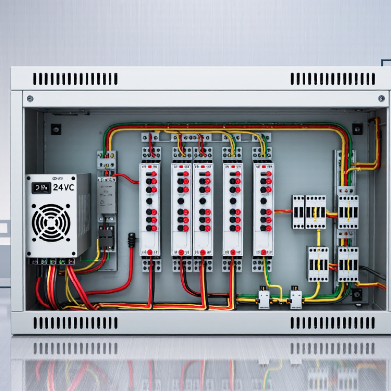
Table of Contents [Hide]
What Is an Analog 4–20 mA Splitter?
Top Analog Splitter 4 20mA Manufacturers
What Is an Analog 4–20 mA Splitter?
An analog 4–20 mA splitter receives one current-loop signal and creates two or more matching outputs. The input represents a measured range, such as 4 mA for zero flow and 20 mA for maximum flow. A splitter allows one transmitter to serve a controller, display, recorder, or alarm system at the same time. Isolated models separate circuits electrically. This helps reduce ground-loop noise and protects sensitive instruments. Non-isolated models can suit simpler panels with a shared reference.
In field work, I check output accuracy with a calibrated loop meter. A 12 mA input should produce a proportional output, not a random near-value. I also verify supply voltage, load resistance, response time, and input burden. A quality manufacturer should publish tolerance data, wiring diagrams, isolation ratings, and test procedures. Clear documentation often matters as much as the enclosure. I have seen installations fail because the splitter was selected by signal type alone. The current range looked correct, but the connected load exceeded compliance limits. Perfect designs are uncommon. Careful checking still prevents expensive surprises.
Tips: Confirm whether outputs are isolated. Check terminal polarity before powering the loop. Test at 4, 12, and 20 mA. Leave spare panel space for ventilation. If noise remains, inspect shielding and grounding rather than blaming the splitter immediately.
How Analog 4–20 mA Splitters Work
Top Analog Splitter 4 20mA Manufacturers
An analog 4–20 mA splitter receives one measured loop signal and creates two or more controlled outputs. Inside, an input resistor converts loop current into a small voltage. An amplifier then isolates and duplicates the signal. Each output drives its own receiver, such as a controller, recorder, or alarm module.
The loop remains meaningful at zero. A 4 mA signal represents the lower measurement range, while 20 mA represents the upper range. Current below about 3.6 mA or above 21 mA may indicate a fault under NAMUR NE 43 guidance. That detail matters in a noisy cabinet. A broken wire should not look like a normal zero reading.
Isolation is the difficult part. Transformers, optocouplers, or modern capacitive barriers separate signal grounds and reduce ground-loop errors. Engineers must check input burden, output compliance voltage, accuracy, response time, and temperature drift. A splitter can be accurate on paper yet fail when several receivers share limited loop power.
The 2024 World Robotics report recorded 541,302 industrial robot installations during 2023, showing continued demand for dependable automation signals. Market analysis from MarketsandMarkets projects the industrial automation market to grow from about USD 205.9 billion in 2024 to USD 395.1 billion by 2029. More devices mean more signal paths.
In field work, I still verify every terminal with a loop calibrator. Datasheets sometimes hide assumptions. A 4–20 mA splitter is simple, but installation mistakes are not.
Key Specifications for Selecting a Splitter
When selecting a 4–20 mA analog splitter, start with the signal path, not the catalogue price. Confirm the input range, output ranges, and whether outputs are active or passive. A powered transmitter can fail when a passive output is connected incorrectly. Ask for input-to-output isolation, channel-to-channel isolation, and the test voltage. These details protect sensitive controllers from ground loops and unexpected potential differences. Keep the wiring practical.
Accuracy should be stated as a percentage of span, with temperature drift listed separately. For a 4 mA signal, a small zero error can distort low-flow measurements significantly. Check repeatability, linearity, response time, and maximum load resistance for every output. A long cable and several receiving instruments can consume the available loop voltage. Calculate the burden at 20 mA, not at the nominal operating point. That mistake is common. Review supply tolerance, reverse-polarity protection, short-circuit behavior, and power consumption.
In plant installations, DIN-rail mounting, removable terminals, and clear channel markings reduce commissioning errors. Select a manufacturer that publishes calibration methods, inspection records, and traceable test data. Independent verification is valuable when the splitter feeds safety-related or tightly controlled processes. I have seen neat specifications hide vague overload limits. Request actual curves and sample test reports. Do not rely on impressive adjectives. A careful technical review may reveal that a cheaper unit needs extra isolation modules. That changes the real cost.
Leading Manufacturers and Their Product Strengths
Top Analog Splitter 4 20mA Manufacturers
Leading manufacturers of analog 4–20mA splitters usually focus on signal stability, isolation, and simple field maintenance. Their strongest products separate one transmitter signal into two or more usable outputs. This helps control panels, recorders, and monitoring systems share the same process value.
Experienced manufacturers often provide galvanic isolation between input, outputs, and power circuits. That matters near variable-speed drives, relay cabinets, and long cable runs. Many units support configurable ranges, such as 0–20mA or 4–20mA, with low conversion error. Clear terminal labels and removable connectors also reduce wiring mistakes during commissioning.
Field testing reveals practical differences. A reliable splitter should maintain a steady output when the input changes slowly or quickly. Some manufacturers publish temperature drift, response time, and load resistance data instead of vague performance claims. That documentation shows technical confidence. However, installation quality still matters. Poor shielding, shared grounding, or an undersized power supply can weaken an excellent device. Compact housings save cabinet space, but tiny adjustment switches may frustrate technicians wearing gloves. This is easy to overlook. Before purchasing, engineers should compare isolation ratings, channel capacity, calibration access, and support quality. A product with slightly wider specifications may not perform better in every cabinet. Real conditions deserve more attention than a polished data sheet.
Top Analog Splitter 4–20 mA Manufacturers: Product Strengths
A 4–20 mA splitter receives one industrial current-loop signal and provides two proportional output signals. The chart shows valid loop-current levels across the standard operating range, from the live-zero value of 4 mA to the full-scale value of 20 mA.
Typical product strengths in this category include galvanic isolation, accurate signal transmission, HART transparency, DIN-rail mounting, 24 V DC operation, and support for single-input to dual-output configurations.
Applications and Installation Considerations
Top Analog Splitter 4 20mA Manufacturers: Applications and Installation Considerations
Analog 4–20 mA splitters serve tanks, pumps, boilers, and dosing skids. They copy one transmitter signal for separate control and monitoring systems. A pressure transmitter may feed both a PLC and a safety display. This prevents extra process connections. Grand View Research valued the industrial automation market at USD 211.74 billion in 2023, with a projected 10.5% annual growth through 2030. More connected equipment means more signal-routing decisions. Signal paths multiply.
Select a splitter with suitable input impedance, output isolation, and loop-power capacity. Galvanic isolation matters near variable-frequency drives and motor cables. Keep signal wiring separate from power conductors. Use shielded twisted pairs, and ground shields according to the site standard. Check polarity twice. A reversed pair can look like a dead instrument. Install the device inside a clean, ventilated cabinet, away from hot terminals and condensation. Leave space for ferrules and test probes.
MarketsandMarkets projects the process automation market to grow from USD 85.7 billion in 2023 to USD 116.7 billion by 2028. That forecast supports careful expansion planning, not automatic reliability. During commissioning, record input current, each output current, and the receiving device’s displayed value. Test 4 mA, 12 mA, and 20 mA points. A neat drawing can still hide a scaling error. In practice, many failures begin with rushed labeling or an unverified common return. Reference: Grand View Research, Industrial Automation Market Size Report, 2024; MarketsandMarkets, Process Automation Market Report, 2023.
| Application Area | Typical Input Signal | Typical Output Configuration | Common Equipment or Process | Key Installation Considerations | Recommended Verification |
|---|---|---|---|---|---|
| Process Measurement | One active or passive 4–20 mA transmitter loop | Two electrically isolated 4–20 mA outputs | Pressure, level, flow, and temperature transmitters | Confirm whether the transmitter requires loop power from the splitter. Check the total load resistance of the input loop and both output circuits. | Apply known input values near 4 mA, 12 mA, and 20 mA, then compare both outputs with calibrated meters. |
| Control and Monitoring | 4–20 mA process variable from a field instrument | One output to a PLC or DCS and one output to a local indicator | Control valves, supervisory displays, and control-room monitoring | Use isolated outputs when the PLC, DCS, or indicator has a different ground reference. Verify input resistance and voltage compliance for each receiving device. | Test the signal at the splitter terminals and at the receiving equipment while all devices are connected. |
| Hazardous-Area Interface | 4–20 mA signal from a field transmitter | Galvanically isolated output circuits, subject to system certification | Petrochemical, chemical, and energy processing areas | Select equipment with the required hazardous-area, intrinsic-safety, or galvanic-isolation approvals. Follow the installation method and wiring limitations specified for the site. | Check approval markings, entity parameters where applicable, grounding arrangements, and loop continuity before energizing. |
| Remote Data Acquisition | 4–20 mA signal from a sensor or transmitter | One output to a remote I/O module and one output to a data logger | Water treatment, environmental monitoring, and utility systems | Consider cable length, voltage drop, electromagnetic interference, and surge exposure. Use shielded twisted-pair cable where appropriate. | Measure the current at both output terminals and confirm stable readings during normal cable routing and operating conditions. |
| Signal Distribution | Standard 4–20 mA analog signal | Two or more proportional outputs, depending on the device design | Distribution of one measurement to separate control, alarm, and recording systems | Check whether each output is active or passive. Do not connect an active output to an input that supplies loop power unless the circuit design permits it. | Verify output polarity, scaling, zero point, span, and the response of every connected input. |
| Temperature Monitoring | 4–20 mA output from a temperature transmitter | Isolated 4–20 mA outputs for controller and display | RTD or thermocouple transmitter applications | Install the splitter away from high-temperature surfaces and high-current switching equipment. Confirm that the transmitter range matches the receiving-system range. | Use a calibrated temperature simulator or current source to check linearity at multiple points. |
| Panel Installation | Single or dual 4–20 mA loop connection | DIN-rail mounted signal distribution module | Control cabinets, marshalling panels, and instrument panels | Provide adequate clearance for wiring and ventilation. Secure the device to the correct DIN rail and label all terminals before commissioning. | Inspect terminal tightness, conductor identification, polarity, and continuity against the approved wiring diagram. |
| Power Supply Arrangement | 4–20 mA input requiring loop excitation | Outputs powered by an external DC supply or by the receiving loop | Two-wire transmitters and distributed instrumentation systems | Confirm the required supply voltage, current capacity, polarity, and minimum operating voltage. Account for voltage drops across the transmitter, splitter, cable, and receiver. | Measure the supply voltage under load and verify that the loop remains within the specified compliance range. |
| Grounding and Isolation | 4–20 mA signal with possible ground-potential differences | Galvanically isolated input and output channels | Systems with separate power supplies, long cable runs, or multiple control panels | Use isolation to reduce ground loops and unwanted circulating currents. Ground cable shields according to the site grounding standard, commonly at one designated end. | Check resistance to protective earth where required and observe the signal for noise with all circuits operating. |
| Calibration and Commissioning | Simulated 4–20 mA input | Proportional duplicated outputs | Factory acceptance tests, loop checks, and maintenance activities | Use a calibrated loop source or process calibrator. Record zero, span, output deviation, and alarm behavior before placing the loop into service. | Document readings at 4 mA, 8 mA, 12 mA, 16 mA, and 20 mA, or at the points required by the project specification. |
| Environmental Protection | 4–20 mA signal in industrial conditions | Enclosed or open-panel signal splitter | Outdoor cabinets, humid areas, dusty plants, and vibration-prone equipment rooms | Confirm the enclosure rating, operating temperature, humidity limits, vibration suitability, and corrosion protection. Keep wiring entrances sealed where necessary. | Inspect the enclosure, cable glands, terminal condition, and operating temperature during a representative running period. |