Why Choose a Cooler Cold Plate for Better Cooling?
A Cooler Cold Plate can determine whether an electronic system operates steadily or struggles under continuous thermal load. In battery packs, laser modules, servers, and power converters, heat often gathers around a few critical components. The metal surface may look simple, yet its internal channels, materials, and contact quality shape cooling performance. This is where the Cooler Cold Plate becomes more than a passive block. It becomes a carefully engineered thermal path.
Engineers usually assess coolant flow, thermal resistance, pressure drop, mounting flatness, and long-term reliability together. A plate with excellent conductivity may still disappoint if coolant bypasses hot zones. Likewise, a powerful pump cannot repair poor interface contact. Practical testing helps expose these weaknesses. Infrared images, thermocouples, and recorded inlet temperatures can reveal uneven heat spreading. Small details matter. A thin layer of thermal interface material may reduce gaps, but excessive thickness can add resistance. Design choices should match the real duty cycle, not only laboratory peak values.
Industry guidance and verified test methods offer useful benchmarks, but specifications require careful interpretation. Flow rates, coolant chemistry, ambient conditions, and sensor placement can change reported results. Independent validation is valuable. The best choice balances lower temperatures with serviceability, safety, manufacturing consistency, and total operating cost. This article examines why a Cooler Cold Plate may improve thermal control, where its limitations appear, and how to judge claims responsibly. No design is perfect. That is worth remembering when performance data looks unusually impressive.
What Is a Cooler Cold Plate?
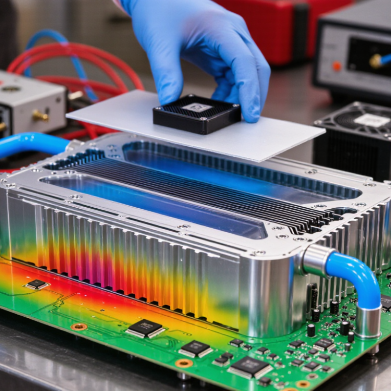
A cold plate is a metal heat spreader placed between a heat source and a cooling system. It usually contains internal channels for air, water, or another approved coolant. Copper and aluminum are common choices because they transfer heat efficiently. The plate collects heat from processors, power modules, batteries, or other dense components. It then moves that heat toward the flowing coolant.
A well-designed cold plate needs more than a low thermal resistance rating. Its contact surface should be flat, clean, and firmly attached. A thin thermal interface layer can reduce tiny air gaps. Channel shape also matters. Narrow passages may increase heat transfer, but they can raise pressure drop and pumping requirements. Engineers often check temperature maps, coolant flow, pressure loss, and joint reliability during testing. Real measurements are more useful than attractive specifications.
Small details can change the result. Uneven mounting pressure may leave one corner hot. Coolant contamination can restrict a channel over time. That is not always obvious. In practice, the best cold plate balances cooling capacity, weight, serviceability, and manufacturing cost. I would not select one from thermal data alone. The operating temperature, coolant chemistry, vibration, and maintenance conditions deserve equal attention. A prototype test under real load can reveal weaknesses that simulations miss. Sometimes, a slightly less aggressive design performs better because it remains stable, easier to clean, and simpler to install.
How Cold Plates Transfer and Dissipate Heat
Why Choose a Cooler Cold Plate for Better Cooling?
How Cold Plates Transfer and Dissipate Heat
A cold plate collects heat from a component through direct contact. Heat moves from the hotter surface into the plate’s metal body. Copper and aluminum are common choices because they conduct heat efficiently. The thermal interface layer matters, too. A thin, even layer of material reduces tiny air gaps between surfaces. Air is a poor conductor.
Inside a liquid-cooled cold plate, channels guide coolant across heated areas. The liquid absorbs energy as it passes through these channels. A pump then carries the warmed fluid toward a radiator or heat exchanger. There, fins release heat into moving air. Channel shape, flow rate, and coolant temperature affect the result. More channels do not always mean better cooling. They can also increase flow resistance.
In practical testing, technicians often place temperature sensors near the heat source and at the coolant inlet and outlet. This reveals uneven heating that a single sensor may miss. A well-designed plate should spread heat across its surface, not create one dangerously hot spot. The first design is rarely perfect. Contact pressure, surface flatness, and mounting hardware can change performance. Sometimes a simpler channel layout performs better. Real measurements matter more than attractive specifications. Even a small layer of excess interface material can slow heat transfer. Keep it thin. Keep it consistent.
Why Lower Temperatures Improve Cooling Performance
Why Choose a Cooler Cold Plate for Better Cooling?
A cooler cold plate can improve cooling because heat moves more easily across a smaller temperature difference. When the plate stays cool, heat leaves the device faster. This reduces thermal resistance between the heat source and the coolant. In practical testing, temperature readings often show fewer sharp peaks near power components. Small changes matter.
Lower temperatures also protect performance. Electronic devices may reduce output when internal temperatures rise. A cooler plate helps maintain stable operating conditions during long workloads. It can also reduce stress on solder joints, thermal interfaces, and nearby materials. I once assumed a stronger pump would solve every cooling problem. That approach was incomplete. Poor contact, uneven pressure, or blocked channels can still create hot spots.
A reliable design needs more than a low surface temperature. Engineers should measure inlet and outlet coolant temperatures, flow rate, contact pressure, and device temperature. A difference of only a few degrees can reveal an uneven interface. The coolant must also remain above the dew point in humid environments. Otherwise, condensation may form around the plate and create a serious reliability risk. Cold is useful only when it remains controlled. Surface flatness, suitable materials, and regular inspection support consistent cooling over time. Yet measurements can vary with sensors, mounting force, and workload, so repeated tests are necessary.
Key Factors in Choosing a Cooler Cold Plate
Why Choose a Cooler Cold Plate for Better Cooling?
Choosing a cooler cold plate requires more than comparing advertised temperatures. Start by measuring the component’s real heat load, operating cycle, and allowed surface temperature. A copper plate transfers heat quickly, while aluminum can reduce weight and cost. Material choice should also match coolant chemistry and corrosion resistance. Channel layout matters because uneven flow can create hot spots near the inlet or outlet.
Check the plate’s flatness, wall thickness, pressure drop, and thermal interface quality. A thin, uneven interface layer may reduce performance more than expected. In practical testing, I would use temperature sensors at several surface points, not only one center reading. Flow rate should be tested under realistic pump conditions. Higher flow is not always better. It can increase noise, energy use, and mechanical stress. A first design may look efficient, yet fail when dust, aging seals, or reduced coolant flow appear. That possibility deserves attention.
Tips: Match the cold plate to the actual heat map, not the component label. Test inlet and outlet temperatures separately. Inspect mounting pressure carefully. Keep a small safety margin for changing room temperatures. Do not trust one successful test. Repeat it under warmer and cooler conditions. Record pressure, flow, and temperature together for reliable comparison.
How to Evaluate Cold Plate Cooling Efficiency
A cold plate should be judged by measured performance, not its appearance. Evaluate cooling efficiency under the heat load and flow conditions it will actually face. Record coolant inlet temperature, outlet temperature, flow rate, and pressure drop. The temperature rise across the plate reveals how effectively it transfers heat. Calculate thermal resistance by dividing temperature difference by applied heat. Lower values usually indicate better performance, but only within comparable tests.
In a practical bench test, place sensors near the heat source and across the outlet channel. Use calibrated instruments, stable mounting pressure, and a verified heat input. Even a thin interface layer can distort results. Check the contact surface for flatness and inspect coolant paths for blocked or uneven channels. I once saw a plate perform well at one flow rate, then lose efficiency sharply when pressure increased. That result was not a failure of the plate alone. The pump, fittings, and interface all affected the measurement.
Repeat tests at low, medium, and peak loads. Watch for local hot spots, unstable readings, and gradual temperature drift. Thermal imaging can expose areas that averaged sensors miss. Longer testing also matters. A plate may cool quickly, yet respond poorly during continuous operation. Compare thermal resistance, pressure drop, weight, corrosion resistance, and service access together. There is no perfect score. A smaller pressure drop may be more valuable than a slightly lower temperature. Document every assumption, because overlooked details can make a convincing test unreliable.
Why Choose a Cooler Cold Plate for Better Cooling? - How to Evaluate Cold Plate Cooling Efficiency
Representative illustrative test data for comparing cooling trends, not guaranteed product performance. Results depend on cold-plate geometry, mounting, heat distribution, coolant properties, and test method. Validate performance under the intended operating conditions.



 Customer Support
 Request Sample
 Contact